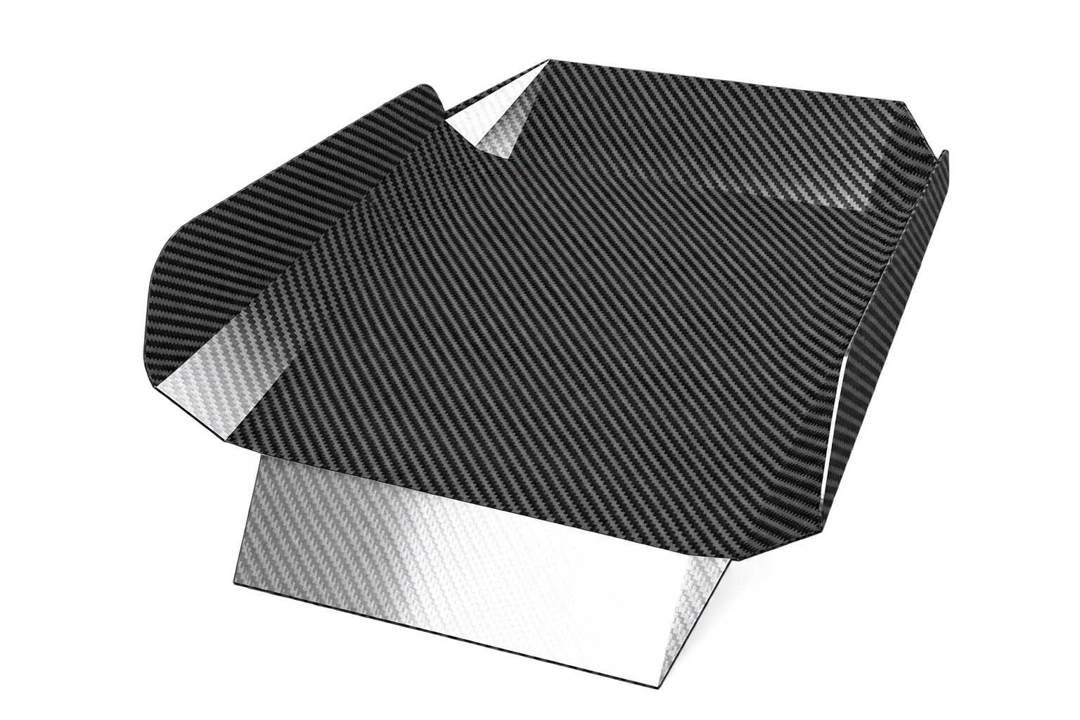
A mounting plate can look finished in CAD while its connection to the assembly remains undecided. Before asking for a laminate or a production sample, make the joint reviewable: show the surrounding parts, explain the loading and identify what the first test must prove. This editorial checklist helps turn an attractive flat panel into a clearer engineering brief.
1. Draw the load path through the assembly
Share an assembly view as well as the plate drawing. Mark the equipment being supported, the attachment points and the surfaces that contact the plate. Explain the operating positions, any offset between the supported item and its mounting surface, and the directions in which loads may act. Include available load cases rather than only the equipment's mass.
Separate a fit-check prototype from a structural development sample. A plate that assembles correctly has answered a geometry question; your team still needs a defined method for judging stiffness, movement and durability in the intended application. Record which questions remain open before selecting the sample route.
2. Define the complete fastening stack
Show the proposed bolt, washer, spacer, insert or bonded bracket in section. Identify access for tools, the mating material and how the assembly will be serviced. Ask the joint reviewer to assess local contact, hole geometry, edge distance and the proposed tightening procedure together. Do not copy a torque setting from a different assembly without project-specific review.
Choose which component locates the assembly and which features provide clearance. Put those decisions on the drawing, including the datum scheme and inspection method for the important hole pattern. Check the assembled tolerance stack before tightening every individual dimension.
3. Specify structural direction separately from appearance
Hexcel's technical guide explains that fiber orientation affects a laminate's mechanical response.
In the development brief, distinguish the cosmetic weave direction from the structural reference direction. Mark a reference axis on the part drawing and request the proposed laminate identification, thickness basis and revision. Ask the engineering team to justify the layup against the agreed load cases; a photograph of a similar plate is a visual reference, not a design calculation.
Hexcel — Prepreg Technology: fiber orientation ↗4. Make bonding and interface preparation explicit
FAA guidance emphasizes controlled surface preparation for bonded structures. This is engineering context, not certification of an industrial plate.
If the design uses adhesive, agree who selects it, who prepares each surface and how the process will be recorded. Request a review of the intended temperature, moisture exposure, cleaning products and disassembly needs. For a metal interface, include a specific question about electrical isolation and corrosion protection rather than assuming the visible finish resolves compatibility.
FAA — AC 20-107B, section 6.c: structural bonding ↗5. Test the joint you intend to manufacture
Define the sample fixture, mating parts, fasteners and assembly sequence before the test. Write down the loading, environment, measurements and acceptance criteria your engineering team requires. Agree how to document the condition before and after testing, and how a failed result will lead to a design decision.
Record changes to holes, hardware, laminate or bonding as revisions. Review their effect on the agreed validation before carrying an earlier result forward. For a shaped part requiring new tooling, also freeze the forming process and tooling basis before formal mold design. A useful review package contains:
- Assembly section, load cases and critical interfaces.
- Hole pattern, datums, hardware and tightening proposal.
- Laminate reference axis, identification and revision.
- Bonding, surface preparation and interface questions.
- Sample configuration, test plan and acceptance criteria.